
To read a photometric diagram at home, first, examine the site plan, noting where lighting fixtures are positioned. Identify calculation points that measure foot-candle levels, which indicate brightness. Utilize shaded views to understand light distribution, where red shows bright areas and blue signifies darker spots. Analyze the lighting schedule for fixture specifications, including wattage and lumen output. Making adjustments based on these findings guarantees adequate illumination for your space, leading to informed lighting design choices as you explore further insights.
Key Takeaways
- Understand the site plan first to identify lighting fixture locations and calculation points before reading the photometric diagram.
- Pay attention to average foot-candle values to ensure sufficient illumination for different tasks in each area.
- Use ISO-lines to analyze areas of equal illumination, assessing how light is distributed throughout the space.
- Look at shaded views and heat maps to identify bright and dark spots, guiding necessary adjustments in fixture placements.
- Refer to the lighting schedule for fixture specifications and ensure adequate wattage and lumen output for your requirements.
Key Concepts to Understand Photometric Diagrams
Understanding photometric diagrams is essential for anyone involved in lighting design or application. A photometric diagram provides an overview of light fixtures, illustrating their luminous output in lumens. This metric indicates the overall brightness available in a space. Average footcandle values measure illumination on specific surfaces, ensuring that lighting meets task requirements. Key to interpreting these diagrams, ISO-lines connect points of equal illumination, guiding users in evaluating light distribution. Furthermore, the shaded view, or heat map, offers a visual representation of light concentration, highlighting areas needing adjustments. A lighting schedule details fixture specifications such as wattage and lumen output. By grasping these concepts, users can optimize lighting design effectively, enhancing both aesthetics and functionality within any environment. A dimmable functionality ensures that users can adjust lighting levels to create the desired ambiance and meet specific needs.
Starting With the Site Plan

The site plan acts as a pivotal reference point in the process of reading a photometric diagram, offering an extensive layout of the project area and the positioning of lighting fixtures. Typically found on the first page of a photometric report, the site plan features lighting fixtures marked with bright symbols, often as red dots, aiding in easy identification. It also highlights calculation points that indicate foot-candle levels, showcasing where light intensity is measured throughout the space. Essential statistics, including maximum, minimum, and average foot-candle levels, are provided within the calculation zone, enabling an understanding of light distribution. A thorough comprehension of the site plan is vital for evaluating how effectively light illuminates different areas within the project. LED strip lights are known for their energy efficiency, which can be an important factor when considering the overall lighting plan for a site.
Recommended Products

TECHNOLOGY: The diffuse polycarbonate lens provides smooth, linear illumination which is designed to resemble the classic look of a 1-lamp fluorescent fixture

TECHNOLOGY: The diffuse polycarbonate lens provides smooth, linear illumination which is designed to resemble the classic look of a 2-lamp fluorescent fixture

TECHNOLOGY: The diffuse polycarbonate lens provides smooth, linear illumination which is designed to resemble the classic look of a 2-lamp fluorescent fixture
Identifying Calculation Points and Foot-Candle Levels

While traversing a photometric diagram, identifying calculation points and their corresponding foot-candle levels is essential for ensuring adequate lighting throughout the space. Calculation points serve as designated locations where foot-candle measurements are taken, reflecting light intensity at various spots. Each calculation point is linked to a specific foot-candle value, which indicates whether the lighting design meets project needs. Typically, diagrams showcase a calculation zone summarizing maximum, minimum, and average foot-candle levels. Recognizing high and low foot-candle readings allows for appropriate adjustments in fixture positioning, ensuring uniform light levels and avoiding excessively bright or dark areas. By consulting the tabular format of foot-candle readings, one can make informed design decisions for ideal illumination in any environment. For effective lighting fixture selection, consider energy-efficient fixtures that are compatible with LED bulbs, offering both cost-effective and environmentally friendly solutions.
Recommended Products
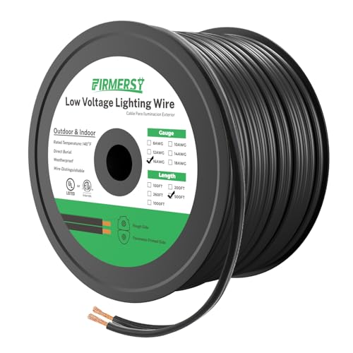
SPECIFICATION: 500-Feet 16AWG*2C, Black, Maximum working voltage: 300V, Great for uses with 30 volts or less, Flexible and easy to strip
3 BRIGHTNESS LEVELS: A touch-sensitive switch allows you to easily switch between three different brightness levels with ease. It has a max output of 380 lumens, bright enough for your office, desk, or dorm.

Item Package Dimension: 3.15L x 2.36W x 1.38H inches
Utilizing the Shaded View for Light Distribution
Utilizing the shaded view in a photometric diagram offers an extensive perspective on light distribution across a given space. This representation highlights areas of varying luminance, with red indicating high illumination and blue showing dark spots. ISO-lines connect points of equal light levels, clearly demonstrating the light spread and intensity throughout the area. Identifying these dark spots helps designers pinpoint where additional lighting is necessary, while recognizing bright zones aids in preventing excessive lumen output. This heat map of light distribution enables efficient planning, ensuring uniform illumination. Ultimately, understanding the shaded view is essential for making informed decisions about fixture placement and optimizing lighting design for desired space utilizations and functionality. For those interested in home automation, selecting a 3-Way Smart Dimmer Switch can further enhance lighting control by offering precise dimming and remote accessibility.
Recommended Products
EASY INSTALL: Easily replaces your existing switch in as little as 15 minutes; NEUTRAL WIRE REQUIRED

MOST CONNECTED: Caseta connects with more leading smart home devices - including Alexa, Apple Home, Google Assistant, Sonos, Ring, Serena shades and more - than any other smart dimmer light switch brand (Lutron Smart Hub, L-BDG2-WH, required)
MOST CONNECTED: The Caseta Smart Dimmer Switch connects with more leading smart home devices - including Alexa, Apple Home, Google Assistant, Ring, Serena shades, and Sonos - than any other smart light switch brand (Lutron Smart Hub required)
Interpreting the Lighting Schedule
A well-structured lighting schedule is an essential tool for anyone involved in lighting design, providing key details about each fixture’s specifications, such as wattage, voltage, and lumen output. This schedule specifies the number of each type of light fixture needed for various areas, ensuring that the desired amount of light is achieved. In addition, it outlines the beam angle and placement recommendations, which guide the best installation for maximum light output and distribution. By using the lighting schedule, one can evaluate energy consumption based on fixture wattage, affirming the design’s efficiency. Furthermore, it supports compliance with design intentions, making it a must-have for successfully interpreting and implementing lighting strategies in any project. Dimmable downlights offer enhanced flexibility in brightness levels, allowing for tailored lighting experiences that match specific mood settings.
Recommended Products

Updated Traditional: This 10-light chandelier's design is light and airy with refined details

Solid Silver construction, high performance facade LED wall mount light. Available in customizable specs, including light direction (straight up or down, away from wall, or towards the wall)

Modern Style: This 14-light LED linear chandelier is modern minimal with a nod to Art Deco
Making Adjustments Based on Findings
Once the lighting schedule has been established and the initial assessments are conducted, it’s important to make adjustments based on the findings gathered from the photometric diagram. First, assess the illuminance levels indicated by foot-candle readings, ensuring areas are bright enough for ideal visibility and comfort. Next, evaluate the color rendering index (CRI) to confirm the fixtures display colors accurately; adjust as needed for enhanced vibrancy. Examine fixture performance details, focusing on beam angles and spacing to achieve even light distribution, while minimizing excessively bright or dim spots. Finally, utilize heat map visuals to identify and rectify hotspots or dark areas by repositioning fixtures or adding additional lighting to create a harmonious and functional home environment. Consider using energy-efficient recessed lights to not only adjust the lighting but also to save on utility bills and enhance the longevity of your lighting setup.
Recommended Products

Commercial Ice Machine Nugget Style by Scotsman NH0622A-1+B322S: High Ice Production Produces up to 644 lbs of nugget ice per day at 70°/50° and 507 lbs at 90°/70°, ensuring a steady supply for busy environments.

Commercial nugget ice maker, Ice and Water Dispenser with Storage (HID207AX-1+HSTCD16-A): Produces up to 196 lb of nugget-style, Original Chewable Ice daily, ensuring a consistent and ample supply for demanding environments.

Energy and water efficiency: Uses significantly less water and energy than other cube ice machines, exceeding federal energy-efficiency regulations by up to 15 percent.
Frequently Asked Questions
How to Read a Photometric Plan?
To read a photometric plan, one must utilize photometric analysis techniques and light measurement methods, focusing on illumination assessment guidelines for ideal indoor lighting design and outdoor lighting applications by interpreting foot-candle levels and fixture placements.
How to Read a Photometric Polar Diagram?
To read a photometric polar diagram, one must analyze intensity distribution across polar angles, noting lumen output variations. This assessment aids in understanding lighting efficiency and determining the fixture’s application relevance for specific tasks.
What Does a Photometric Diagram Show?
A photometric diagram, like a painter’s palette, reveals illuminance levels across a canvas, showcasing light sources and their dance in design applications, enhancing energy efficiency and illuminating fixture performance with vibrant clarity and precision.
How to Read Light Distribution Chart?
To read a light distribution chart, one must examine light intensity at various angles, identify fixture orientation, assess the beam angle, and determine illumination levels suited for specific application areas, ensuring ideal lighting performance.


